A boost for rural schools in Buenos Aires Province with solar energy
Reading time: 2 min
A boost for rural schools in Buenos Aires Province with solar energy
With climate change being one of the greatest threats of our time, the adoption of renewable energy sources is becoming increasingly essential. In this context, Buenos Aires Province in Argentina has taken the lead with an innovative project that promises to make a significant impact.
The Ministry of the Environment has approved an initiative involving the installation of solar energy systems in 22 rural schools. This project represents a major step towards a more sustainable energy transition, providing access to clean and affordable energy sources in areas with limited resources, also addressing energy vulnerability.

Behind this project lies extensive technical work carried out by the Provincial Directorate of Ecological Transition. This entity has made a significant effort to identify schools that either lack access to an electrical grid or require modernization and maintenance, highlighting the need to improve energy access, particularly in rural schools.
Our engineering team, including experts such as Chloé Coral and Jordi Monge, has played a crucial role in this process. During their mission in Buenos Aires, they visited the area to assess the specific electrical needs of each school, ensuring that the adopted solution is the most suitable for each case.
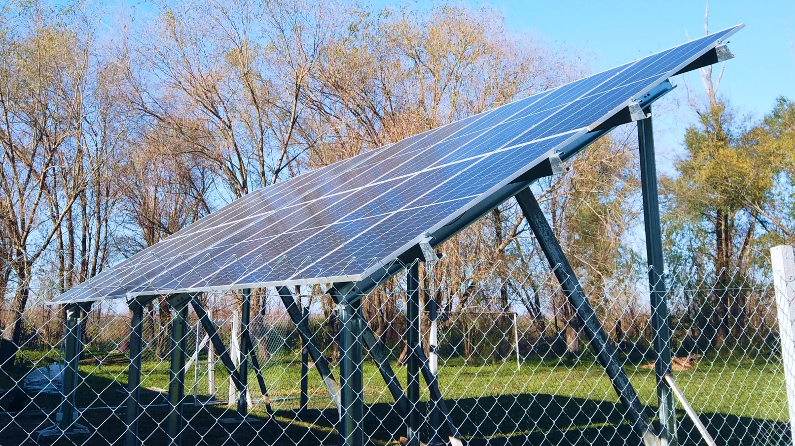
The first phase of this initiative involved a detailed evaluation of the electrical systems in each school to determine the necessary actions. Many of these schools already had photovoltaic panels, but the assessment revealed a clear lack of maintenance and the poor functioning of most solar installations.

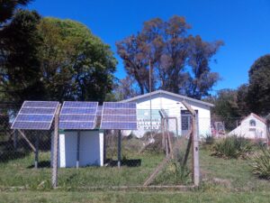
School No. 14 in Pila
Subsequently, in a second phase, the necessary installations and repairs were carried out to ensure a proper electrical system based on clean energy use. This effort will not only improve the quality of education in these schools but will also contribute to a more sustainable future for the community as a whole.
This initiative also highlights the importance of inclusive environmentalism, a concept that seeks to combine environmental protection with social and economic equity. It is a model that could be replicated in other regions and countries, setting an important precedent in the fight against climate change and social inequality.
This approach is particularly relevant for rural schools, which, due to their remote locations away from urban areas, face unique and significant challenges.
The rural schools in Buenos Aires Province, often situated in remote and difficult-to-access areas, face numerous challenges beyond education itself. In many cases, logistical difficulties such as poor road conditions or long distances make student transportation a challenge, especially during bad weather. These conditions can limit regular access to education for many children, increasing inequality in educational opportunities.
 One of the most significant challenges is the lack of basic infrastructure, including access to quality energy.
This deficiency not only affects the school’s ability to provide quality education (for example, through adequate lighting or the use of educational technologies) but also impacts the daily lives and well-being of students and staff.
For this reason, we believe that the renovation of the existing solar installations will represent a qualitative leap in energy generation, which will, in turn, improve the quality of these educational centers.
Discover more projects like this at https://azimut360.coop/projectes-energia-solar/.
Key Challenges of Photovoltaics: Causes, Impact, and Prevention
Key Challenges of Photovoltaics: Causes, Impact, and Prevention

When a photovoltaic installation operates optimally, ensuring a safe and reliable electricity supply, it can become a large-scale power source. However, photovoltaic technology faces major daily challenges in terms of quality, installation, operation, and decommissioning. Below, we describe five main challenges facing photovoltaic technology:
Derating
What is Derating?
Derating refers to the power reduction in photovoltaic inverters caused by environmental factors such as heat, altitude, and voltage. In extreme situations, this phenomenon can even stop production. This effect is especially noticeable in areas with high temperatures.
Causes of Derating
The main causes of derating are:
- Temperature: When inverters generate heat while converting direct current (DC) into alternating current (AC) and the ambient temperature is high, the inverters reduce their power to protect internal components.
- Altitude: At high altitudes, the low air density facilitates ionization at high voltages, affecting inverter performance.
- DC voltage: Maintaining the proper operating voltage range is essential to avoid derating.
How to Prevent Derating
To avoid it, several actions can be taken:
- Proper installation: Follow the manufacturer’s recommendations for ventilation and avoid direct sun exposure.
- Quality of equipment: Choose high-quality inverters with efficient ventilation systems, either by convection or forced ventilation.
- Regular monitoring: Conduct periodic inspections to ensure optimal performance.
LID Effect (Light-Induced Degradation)
What is the LID Effect?
The LID effect refers to the degradation of photovoltaic modules caused by chemical reactions in silicon cells, leading to a loss of power and efficiency during the first months of solar exposure. This can result in a reduction of up to 10% of the initial power.
Causes of the LID Effect
The main cause of this effect is the reaction of boron with elements such as oxygen, iron, or copper present in the silicon cell. While boron is crucial for generating electricity, these reactions reduce electron flow, affecting the module’s efficiency.
Monocrystalline P-type modules are especially vulnerable to LID due to the difficulty in completely eliminating oxygen during the manufacturing process. In contrast, N-type cells, doped with phosphorus, show greater resistance to this effect.
How to Prevent the LID Effect?
- Applying high temperatures and currents.
- Using advanced technologies such as lasers or LEDs.
- Eliminating oxygen within the cell, though this is costly.
- Replacing boron with gallium.
Hotspot
What is a Hotspot?
A hotspot is a localized area within a photovoltaic module that overheats, potentially damaging the module or, in extreme cases, causing a fire. This issue arises from high resistance in a specific area, turning it into an electricity consumer that generates heat, exceeding 200°C.
Causes of Hotspots in Photovoltaic Modules
Hotspots can be caused by internal defects, shading, broken solder joints due to poor manufacturing, or improper handling. Other factors include accumulated dirt and permanent obstacles like trees or chimneys.
Prevention of Hotspots
- Choose materials from recognized brands with certified manufacturing processes.
- Ensure proper transportation of the modules.
- Follow the manufacturer’s instructions during installation.
- Regularly clean the modules according to site conditions.
- Conduct periodic inspections with specialized equipment.
Delamination
What is Delamination?
Delamination refers to the loss of adhesion between the different layers that make up a photovoltaic module. This defect can appear shortly after installation but may worsen over the module’s lifetime.
Causes of Delamination in a Photovoltaic Module
Delamination is usually associated with poor manufacturing or the use of low-quality materials. Additionally, improper transportation and handling during installation increase the likelihood of delamination. Environmental factors such as temperature, humidity, and UV radiation accelerate this process, especially in lower-quality modules.
Detection and Prevention of Delamination
Delamination can be identified through visual inspection, observing color changes in the module, white spots on the front, or bubbles on the back.
How to Prevent Delamination?
- Purchase materials from trusted brands with certified manufacturing processes.
- Ensure proper transportation, keeping the modules palletized and free from additional weight.
- Handle the modules carefully during installation, following the manufacturer’s recommendations.
- Periodically inspect the plant, performing visual checks and using specialized equipment at least once a year.
How Does Delamination Affect Photovoltaic Modules?
When delamination occurs away from the module’s edge, it can affect performance without posing an immediate safety risk. However, if delamination spreads to the edges, it can allow air and moisture to enter, leading to corrosion and irreversible deterioration of the module, which puts the plant’s integrity at risk.
LeTID Effect (Light and Elevated Temperature Induced Degradation)
What is the LeTID Effect?
The LeTID effect is a phenomenon that affects photovoltaic modules, particularly those using PERC cells. Discovered in 2012, it causes a power loss due to sunlight exposure, similar to LID, but occurs at operating temperatures above 50°C, whereas LID occurs at lower temperatures.
Causes of the LeTID Effect and How It Is Detected
Research points to hydrogen as the main culprit. During the cell manufacturing process, hydrogen atoms diffuse from other layers into the active area of the cell. High temperatures in the manufacturing process increase this diffusion, raising the risk of LeTID.
This issue is not visible to the naked eye, as LeTID is detected through an abnormal drop in panel performance. To confirm it, after ruling out other defects such as hotspots or delamination, electroluminescence equipment is used, just like with LID.
Preventing the LeTID Effect
Manufacturers and laboratories are working to better understand and mitigate the effects of LeTID. Some preventive measures in the manufacturing of PERC cells include:
- Using materials with low hydrogen content.
- Reducing temperatures during cell treatment.
- Using thinner wafers.
What You Need to Know
To prevent the effects of LID, hotspots, delamination, LeTID, or derating, it is crucial to carefully select both materials and manufacturers, optimize wafer treatment processes, and apply proper practices in transportation, installation, and maintenance of photovoltaic modules. Preventing and detecting these defects not only ensures greater efficiency and a longer lifespan for installations, but also provides significant long-term economic benefits.
In conclusion, the photovoltaic industry faces complex challenges that affect the durability and performance of installations. However, by using high-quality materials, applying advanced technologies, and ensuring proper maintenance, it is possible to mitigate these issues and ensure that installations operate optimally. At Azimut360, we work to provide comprehensive, tailored solutions for preventing and detecting these defects, ensuring that our clients’ photovoltaic installations not only maximize their efficiency but also extend their lifespan, generating sustainable economic benefits in the long term.
Second Phase of the Solar Photovoltaic Project at MRC/UVRI & LSHTM in Entebbe, Uganda: 45% Solar Fraction Achieved!
Second Phase of the Solar Photovoltaic Project at MRC/UVRI & LSHTM in Entebbe, Uganda: 45% Solar Fraction Achieved!
In Entebbe, a city on the shores of Lake Victoria in Uganda, there has been recent progress in the field of solar energy. With an exceptional 278 kWp photovoltaic generator and 930 kWh of LFP BESS, the biomedical research unit MRC/UVRI & LSHTM has achieved a 45% solar electricity fraction (which translates into savings on electricity bills). This initiative not only increases the sustainable energy generation capacity of the center but also sets a benchmark towards a more sustainable and energy-autonomous future. As the project is now in its second phase, this expansion has been built upon the previous solar photovoltaic installation, which consisted of a 327 kWp self-consumption system.
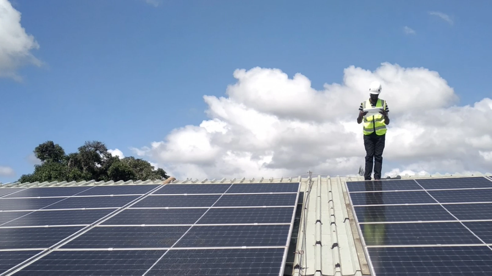
The photovoltaic arrays in this new phase have been placed on the roofs of the CRF Clinic, a newly built clinic by the center, and on the staff houses. Each roof directs all photovoltaic strings to two technical rooms where the solar photovoltaic inverters have been installed. Fuses and SPDs have been placed on both the roofs and inside the technical rooms to protect all DC strings. The AC protections and the remaining electrical and communication panels complete the installation inside the technical rooms. All the electricity generated in the CRF clinic area is transferred to the main site area via a recently installed medium-voltage line, an extension of the existing 11 kV ring of the Unit. A Battery Energy Storage System (BESS) is connected at low voltage directly to the Unit’s main switchboard. This consists of a set of outdoor cabinets, placed on a concrete slab.
What were the objectives of this installation?
The Medical Research Council in Uganda had a dual objective in mind. On one hand, to reduce electricity bills as much as possible, becoming immune to future fluctuations in electricity and diesel prices. On the other hand, and perhaps more importantly, to become carbon neutral and move closer to full energy autonomy.
How did we achieve this?
We conducted a prefeasibility study, which included monitoring the center’s energy consumption patterns. Then, we carried out simulations to optimize the expansion (which included photovoltaics + storage), and finally, we designed and engineered the solution using the highest quality brands available in the market. We concluded that the best area available to place the photovoltaic modules was around the staff houses and the new CRF roof, which also had considerable surface area. Reaching this point required extending the medium-voltage ring that the Uganda Unit already had. A total of 520 photovoltaic modules were installed on 7 roofs. As for the BESS, we opted to install a 300 kVA Power Conversion System (PCS) from the French manufacturer Socomec, along with a total of 930 kWh, divided into 5 outdoor cabinets of 186 kWh each, from one of the leading manufacturers of lithium iron phosphate, CATL. Last but not least, the entire solution is governed by a hybrid controller, which monitors the load at all times, the energy generated by the photovoltaic arrays, and the energy supplied by the grid or generators; this controller is also responsible for commanding the BESS, which will charge or discharge the battery according to the best possible strategy.
The Battery Energy Storage System (BESS)
As mentioned earlier, to store the excess solar photovoltaic energy, we chose the manufacturer Socomec. This is a company with over 100 years of experience in energy conversion, monitoring, and electrical switching. Specifically, the selected solution was the “SUNSYS HES L,” an ESS specifically designed for outdoor environments and renewable energy applications. This solution uses 3 types of cabinets, which are more modular and use less space: an electrical distribution board (AC-Cab), an Energy Conversion Cabinet (C-Cab), and each of the battery cabinets (B-Cab). Being more modular allows the system to easily adapt as needs grow. Moreover, this solution supports configurations that are compatible with both grid-forming and grid-following applications. The C-Cab in this case consisted of six 50 kVA power modules, which can be hot-swapped (i.e., they can be replaced even with the system online) in case of maintenance.
In summary, the solar photovoltaic expansion carried out at the Uganda Unit of MRC/UVRI & LSHTM represents a significant step towards energy autonomy and carbon neutrality. By combining top-class photovoltaic solar module technology with the latest advances in lithium energy storage, this project ensures at least 45% of the center’s energy needs are met from a clean energy source and represents a reference model for future projects in the region.
The involvement of companies like Azimut 360, specialized in promoting sustainable energy solutions and developing projects that encourage a clean energy transition, has been key to the success and future replicability of this initiative, which paves the way towards a greener and more self-sufficient future.

